Battery Sentinel System
Product Use
This Battery Sentinel System is especially developed for use in Battery Electric Vehicles (BEV), which use serially connected 12-Volt batteries in their Traction Battery Stack.
Description
Lead Acid chemistry (Pb-a) batteries should not be charged to individual cell voltage that is higher than 2.40 Volts, this translates to 14.40 Volts for typical 12 V battery that has 6 cells, or for 48 V traction battery which consists of four 12 V batteries connected in series
this is 57.60 Volts Maximum.
It is very important, to limit the maximum individual battery voltage during charging, otherwise the battery will be damaged.
Exceeding this maximum charge voltage results in breakdown of the electrolyte, overheating of the battery and ultimately loss of capacity and reduction of the battery pack useful life.
Battery Overcharge Protection is the most cost effective battery management system, which can be utilized in unison with any type of battery charger.
Batteries in Series
No two batteries are exactly the same, as each
individual cell in the battery has a slightly different capacity.
The battery internal resistance deviates from battery to battery more the closer the battery is to full state of charge.
When several batteries are connected in series to provide higher voltage such as in 48 Volt systems, this difference in internal battery resistance will result in different and unequal voltages across each individual battery in the pack, especially during charging.
For example: While the total battery pack voltage may be 57 Volts, the individual batteries in the pack may be at 14.8V, 14.0V, 14.2V and 14.0V. Because this is still 0.6V below the maximum threshold, the battery charger will continue charging of the pack.
The charger will not shut off until the battery pack voltage is well over 57.6V.
By the time that happens the first battery may reach 15V or more, and will for sure be negatively impacted.
Only if every battery in the pack has individual Battery Overcharge Protection Module that signals the
Master Central Controller to shut off the charging, will every battery in the pack have full overcharge protection.
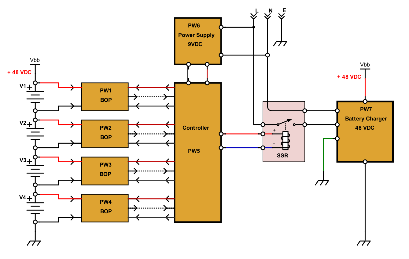
The Battery Sentinel System is Battery Overcharge Protection System that consists of:
- Battery Overcharge Protection Modules (BOPM)
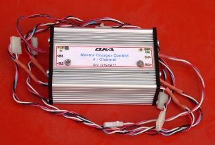
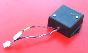
- Master Central Controller
- Servo Power Supply
- Solid State Relay (SSR)
Individual Battery Overcharge Protection Module (BOPM) is installed at each battery in the pack.
Each module is then connected to Master Central Controller (MCC).
The Master Central Controller in turn shuts off the Traction Pack
Battery Charger via Solid State Relay (SSR) at any time the voltage at any individual battery in the pack reaches 14.4V.
When the voltage on all individual batteries in the pack drops below 12.6V each, then the charger is once again turned
ON.
And again when the 14.4V maximum at any battery in the pack is reached the charger is again turned
OFF.
Because of this fully automatic Turn ON / Turn OFF feature, the battery charger can be connected
continually, when the vehicle is not used, and no danger exists of Battery overcharge.
In more advanced versions of the Battery Sentinel System the
Master Central Controller (MCC) can also monitor the time it takes to reach 14.4V, and the time that any battery in the pack drops
back down to below 12.6V.
When the voltage raise from 12.6V to 14.4V is faster than some pre-specified interval, the battery pack is considered to be nearly fully charged and the Battery Charger can be permanently turned
OFF.
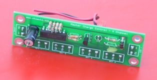
Battery Overcharge Protection Modules (BOPM)
- Generates "Charge ON Command Signal"
- Output is Opto-Isolated from the monitored Battery Voltage
- Two Status LEDs Green = ON, Red = OFF
- Nominal Battery Voltage 12V
- One Module is used for each individual pack Battery
- Four Modules are required for 48VDC nominal Traction Battery
- Operating to Releasing Timing = approximately 1 second
- Over 100,000,000 Electronic Cycles Life
BOPM Connections
INPUT A (large 2 pin connector)
- Monitored Battery positive (+) 12 VDC Nominal [Red]
- Monitored Battery negative (-) 12 VDC Nominal [Black]
INPUT B /OUTPUT (small 3 pin connector)
- Servo Power IN Vbb 9 VDC to 12 VDC (+) [Red]
- OUT = Signal OUTPUT (+) = Charge ON Command [White]
- GND (Common System Ground) (-) [Black]
BOPM Specifications
| Power Supply Voltage (min/max) | VCC | 8 / 16 | V |
| Power Supply Voltage (min/max) | VBB | 8 / 16 | V |
| Output ON Threshold Voltage | VON | <12.6 | V |
| Output OFF Threshold Voltage | VON | >14.4 | V |
| OUTPUT Load current (max) | IL | 10 | mA |
| OUTPUT Signal Voltage (min/max) | VOut | VBB - 1.5 | V DC |
| Power Consumption (LED) | Pon | 160 to 210 | mW |
| Operating Temperature | Ton | 20 to 140 -6 to 60 |
°F °C |
BOPM Pricing
US $ 10.50 each