Solar Charger Option
Option shown on this page is available for all Model Years of OKA NEV ZEV.
Option Description
The OKA Sol 12 is designed to be used with roof top solar panel and the ACG ABBS 48-12 (Active Battery Balancing System) to maintain the four 12 Volt Lead-acid batteries that are connected in series for 48 Volt nominal Battery Stack Voltage at fully charged condition.
It will maintain the Battery Stack at full charge as long as there is at least 5 Watts of Solar Power Input for about 8 hours per day.
It can be used with a single 5 Watt panel, or with 2, 3 or 4 panels with up to 20 Watts of total Solar Power at full sunlight.
All voltage monitoring and fault detection circuitry and functionality is integrated.
The OKA Sol 12 provides charge current to the Auxiliary Battery that is used with the ACG ABBS 48-12.
The ACG ABBS 48-12 employs this Auxiliary Battery to transfer charge to each individual battery in the series connected Battery Stack.
The Solar Charging operation itself is fully automatic.
The OKA Sol 12 Module contains Solid State logic and high efficiency switching regulator.
Background
Whenever several Solar Panels are connected in Parallel to form a higher Current Output, the over all Solar Stack performance is limited by the "weakest" individual Solar Panel in the Stack.
Solar Panels in the stack become mismatched due to following reasons:
- Manufacturing tolerances / defects
- Varying solar exposure (some panels may be shaded)
- Accrued aging differences
- Imbalanced loading
- Panel replacement in the stack
Result of Operation with mismatched Parallel connected Solar Panels:
Capacity and mismatch create charging problems, which reduce battery lifetime.
Capacity and mismatch reduce run time.
System Operating Principle
The OKA Sol 12 is a stand-alone battery charger and voltage regulator for use with 12 Volt Lead-acid battery.
It will limit the Solar Panel output voltage, which can be as high as 40 Volts, to a safe trickle charge voltage of 13.7 Volts maximum.
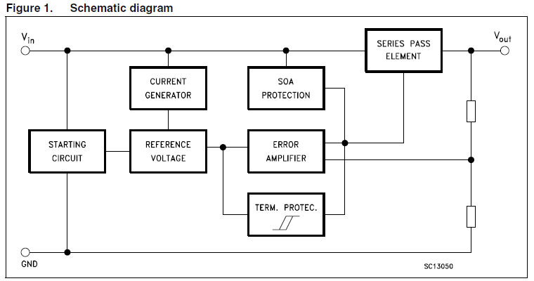
The OKA Sol 12 Module contains a sophisticated circuitry that is shown in Figure 1 below:
Click Image for larger size
Charging works by reducing the high input Voltage that is generated by the Solar Panel(s) to a safe lower voltage level so that the Auxiliary Battery is properly charged.
Charge current is likewise limited to prevent overcharging and to limit electrolyte heating, which results in water depletion.
Not only does OKA Sol 12 Module charge, but if multiple Solar Panels are used, their input into the module is balanced, to prevent Voltage "back flow" to any panel that may be partially shaded. This maximizes the total available energy for charging of the Auxiliary Battery, thus increasing overall capacity.
FEATURES
- Single Sol 12 Basic Unit Balances input from up to Four 12V Solar Panels
- All Solid State Design
- Stack-able and Expandable to Balance Larger Series of Solar Panels
-
Stand-alone Charging Operation:
Requires NO External micro processor or additional Control Circuits - Balancing Current limited by internal logic
- Dimensions: 2 x 2 x 0.75 inches
- Power Consumption: less than ¼ Watt
- Weight: 1.6 ounces (43.5 grams)
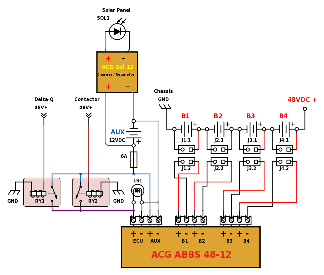
Wiring Diagram
Single Solar Panel 5 Watt Minimum, 20 Watt Maximum
Click Image for larger size
IMPORTANT NOTE:
Auxiliary Battery Negative Pole (AUX -)
and the Solar Charger Negative Output are connected together, but are Isolated from Vehicle Chassis Ground.
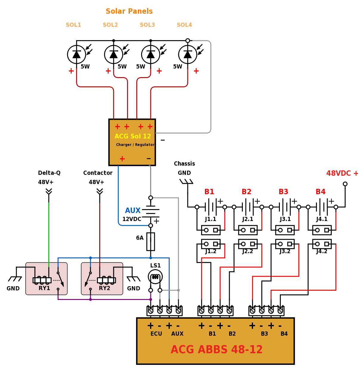
Multiple Solar Panels 5 Watt each, 20 Watt Maximum total
Click Image for larger size
IMPORTANT NOTE:
Auxiliary Battery Negative Pole (AUX -)
and the Solar Charger Negative Output are connected together, but are Isolated from Vehicle Chassis Ground.